Rover Location Database
Ham Radio
- K7BWH
- My Shack
- Hermes SDR
- IC-7100 Fldigi
- FT897d Settings
- FT897d Linear
- TS850 Control
- TS850 Assembly
- VHF Rigs
CAT Control of TS-850s
The Kenwood TS-850s is a terrific ham radio transceiver. It becomes even better when coupled to your computer. Here are some engineering notes about how the parts are connected.
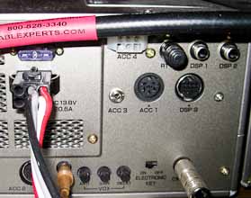
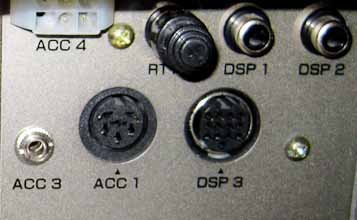
Kenwood TS-850s Radio
Back panel contains ACC-1 connector with serial port. This is designed for Kenwood's IF-232C Interface cable, and outputs TTL level data.
DIN is an abbreviation for Deutsches Institut für Normung, or German Institute for Standardization, which is a German manufacturing industry standards group. DIN connectors are round with pins arranged in a circular pattern. A similar connector was once widely used for PC keyboards.
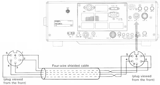
The image above shows the ACC-1 wiring pinout diagram, as shown in the Kenwood Owner's Manual page 47.
| Plug viewed from the front | ||||
| Pin No. | Signal Name | TS-850 Direction | Description | |
| 1 | GND | Signal ground | 0v | |
| 2 | -TXD | Output | Transmit data: the transmit data is the serial data from the transceiver to the computer. The output utilizes negative logic. | 0.16v |
| 3 | -RXD | In | Receive data: The receive data is the serial data from the computer to the transceiver. The input utilizes negative logic. | 5.13v |
| 4 | CTS | In | Clear to Send: This signal is supplied from the computer and is used to inhibit transmit data from the transceiver when tghe computer is not ready. Transmit data is stopped by a logic low. | 5.13v |
| 5 | RTS | Output | Ready to Send: This signal is applied to the computer and is used to inhibit transmit data from the computer when the transceiver is not ready to receive it. Inhibit is requested when the level is low. | 5.13v |
| 6 | n/c | No connection | 0v | |
Add a jumper between pins 4 and 5, strapping together CTS and RTS. This allows the TS-850 to raise its "ready to send" output which enables its "clear to send" input so that it can transmit data. For example, you will not be able to see TxD on pin 2 with an oscilloscope until you add this jumper.
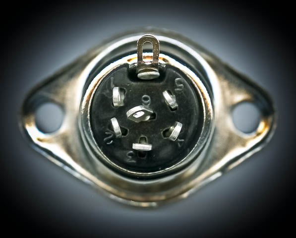
DIN-6 Cable Connector
 Pins
1 through 6 are numbered clockwise when viewed from the back of the transceiver.
Pins
1 through 6 are numbered clockwise when viewed from the back of the transceiver.
The photo at right shows the numbers stamped on the back of a DIN-6 socket. I bought this socket for $2 USD at our local Vetco Electronics store, which features the best selection of cables and connectors in the Pacific Northwest.
Signal Cable
The radio's DIN-6 connector needs an extension cable to reach the Radio Shack adapter. It must convert from DIN-6 at one end to a 1/8" female stereo connector on the other end.
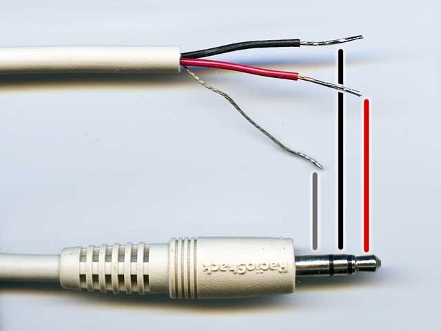 I used a six-foot stereo headphone extension cord from Radio Shack
(similar to 42-2482)
and replaced the male end. How is the connector connected? To figure this out with an ohmmeter, before
making my connections, the native cable wire color codes are shown in the picture here.
I used a six-foot stereo headphone extension cord from Radio Shack
(similar to 42-2482)
and replaced the male end. How is the connector connected? To figure this out with an ohmmeter, before
making my connections, the native cable wire color codes are shown in the picture here.
| Stereo Plug Wiring | ||||
| Jack | Color | Audio | ||
| Sleeve | Bare | Common | ||
| Ring | Black | Right | ||
| Tip | Red | Left | ||
TTL-to-USB Level Converter
Radio Shack part number 200-0546 is "USB Scanner / PC Interface Cable" that will convert the radio's serial datastream into USB port and protocol. Price is $34.99 as of November 2010.
This part replaces an earlier popular equivalent, the Radio Shack 20-047, and the modern part includes a CD with drivers for most Windows platforms including Windows 7.
| Radio Shack Cable Pinout | ||
| Sleeve | Common | |
| Ring | Receive Rx for scanner | |
| Tip | Transmit Tx for scanner | |
This might sound like an optical flatbed scanner, but actually refers to many of the shortwave radio scanners that Radio Shack offers.
Once the software is installed and then the adapter connected, you need to find the COM port number. On Windows 7: Start -> Control Panel -> System -> Device Manager -> Ports -> USB Serial Port (COM3).
The converter's small stereo plug requires an adapter be built to match the 6-pin DIN connector. I cut one end of an audio extension cable, and soldered on the DIN connector: Plug viewed from front: pin 1 =
Serial Port Programming
Published serial port settings are:
4800 bits per second, 1 start bit, 8 character bits, 2 stop bits, no parity
Current Status
1-1-2011: No response is ever seen from the TS-850s. An oscilloscope shows the level converter is sending data, but no replies are returned by the transceiver and no front-panel functions show that a command was received.
I'm reasonably confident my wiring is correct, so my current thinking is the output chip is not working. A good thing to try next is to bring the transceiver to someone with a working setup and see if it functions correctly there.
| < Previous | Page 7 of 9 | Next > |
©1998-2024 Barry Hansen