Rover Location Database
Ham Radio
- K7BWH
- My Shack
- Hermes SDR
- IC-7100 Fldigi
- FT897d Settings
- FT897d Linear
- TS850 Control
- TS850 Assembly
- VHF Rigs
Disassembling a Kenwood TS-850
What if your headphone jack is broken? My jack adapter split up and left parts inside my TS-850. How do you get the damn thing out?
The Kenwood TS-850 is ruggedly well designed to be worked upon with ordinary tools. Here's how to assemble or disassemble the TS-850.
Problem: Broken Headphone Jack
My headphones have a small stereo plug, while my transceiver has a large 1/4" headphone jack. I used a common adapter for conversion.
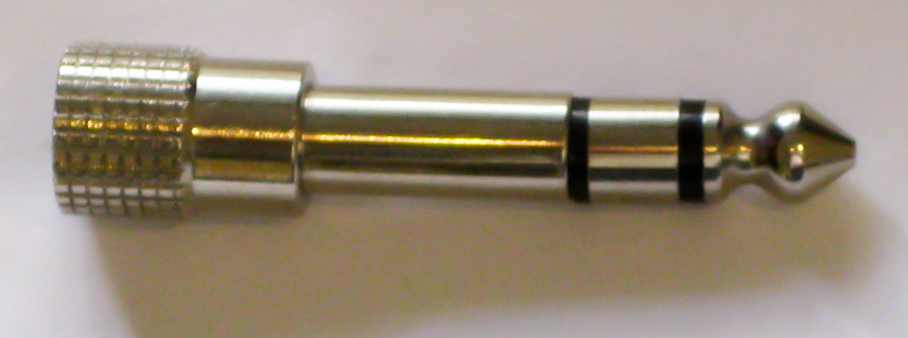
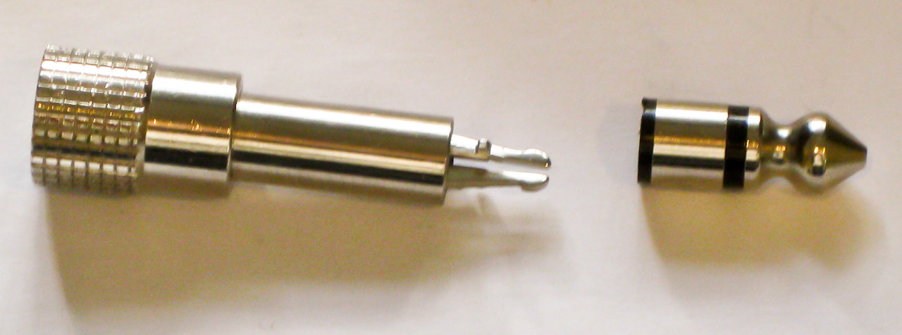
My headphone adapter fell apart (just before a demonstration, of course) leaving the tip deep inside the transceiver. I was unable to fish it out with pliers, hooks, papers clips or anything else. So ... I could not plug in the headphones, and the errant tip turned off the speakers. My transceiver was silent.
Solution: Open the Covers of a TS-850
Here are pictures of the assembly process after fixing the jack. Hopefully the disassembly process will be self-evident by reading the page in reverse order from bottom to top.
Tools needed: Phillips screwdriver, medium
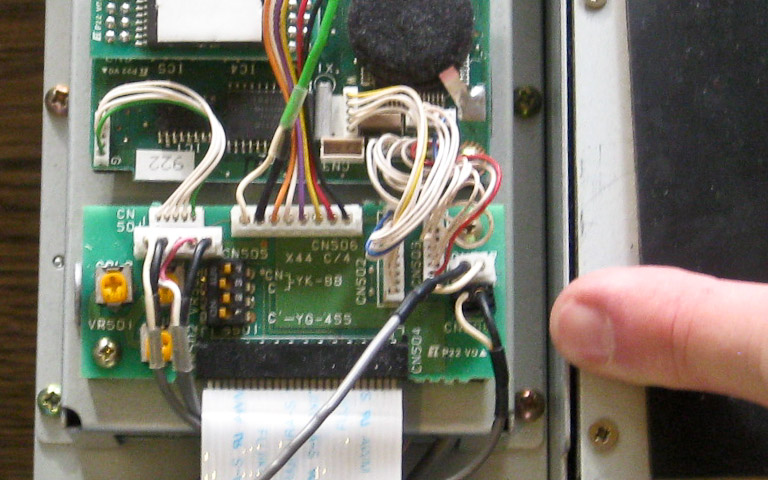
Accessing the Interior of the Jack
 The
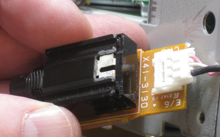
TS-850 headphone jack is a sealed unit soldered to a small printed circuit board (PCB). To gain access,
I pried off the center back portion of its plastic cover. This picture shows the hole that I opened, exposing
a portion of the internal contactor.
The
TS-850 headphone jack is a sealed unit soldered to a small printed circuit board (PCB). To gain access,
I pried off the center back portion of its plastic cover. This picture shows the hole that I opened, exposing
a portion of the internal contactor.
A stiff wire was inserted into this hole, pushing out the errant adapter shrapnel.
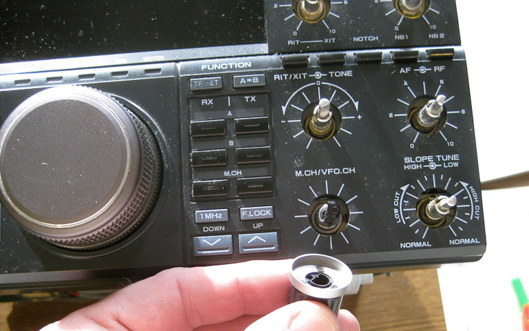
Install Jack Using Retaining Clip
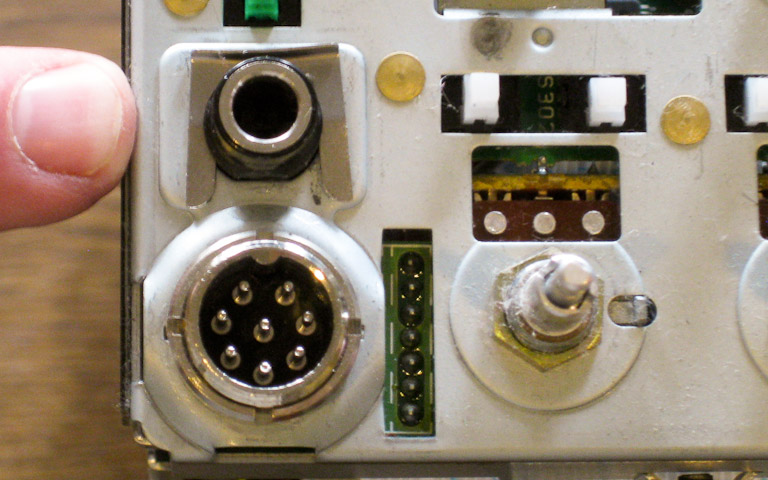 The headphone jack slides into the front panel from the back, and is then held in place by a square chrome
retaining clip.
The headphone jack slides into the front panel from the back, and is then held in place by a square chrome
retaining clip.
To attach the clip, hold the jack in place from the back and slide clip straight down from top, being careful to clear the button above. Don't rotate the clip as it will easily bend.
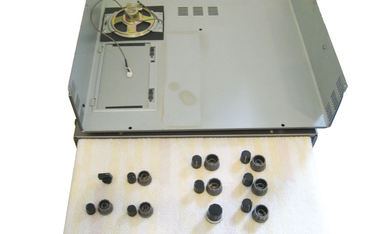
Mount Button Caps
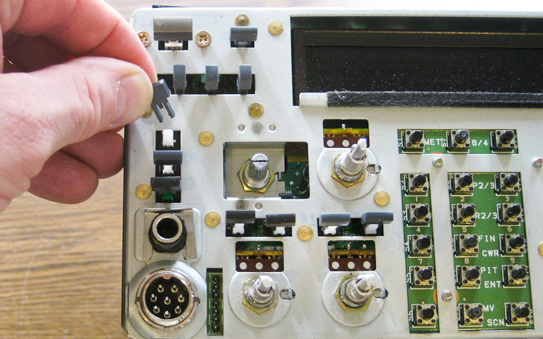 All these little tiny button caps are barely held in place by friction.
They will fly off with no provocation; even their own weight may cause them to drop off and
skitter away under a table. They are small and invisible and tasty to cats.
All these little tiny button caps are barely held in place by friction.
They will fly off with no provocation; even their own weight may cause them to drop off and
skitter away under a table. They are small and invisible and tasty to cats.
Rest the transceiver on its back.
Spread a white towel or sheet under your transceiver to catch the loose bits.
Install Faceplate
Keep the transceiver resting on its back, so faceplate is horizontal and level and facing upward.
Triple-check that all your buttoncaps are in the correct place (check the colors!) and aligned to match the plastic faceplate.
Bring the plastic faceplate straight down, gently working it onto and aligning with the button caps. The faceplate will come down only far enough until its four tabs hit the chassis's retaining clips.
 Gently pry the four plastic tabs upward but only just enough to slip over retaining clip.
There are two tabs on the top and two tabs on the bottom.
Gently pry the four plastic tabs upward but only just enough to slip over retaining clip.
There are two tabs on the top and two tabs on the bottom.
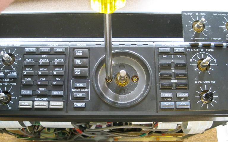 Install the two screws around the main tuning knob.
Install Main Tuning Knob
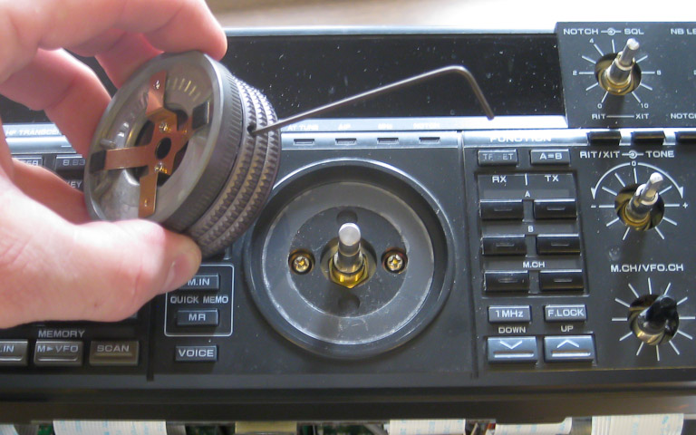 The main tuning knob is held in place with a single set screw.
A standard 1.5mm hex key will fit.
Clean the wiper surface before installation. This helps ensure smooth tuning action.
Install Other Knobs
 All other knobs are a simple press fit. Rotate the control stems fully counter-clockwise and align the
knob arrow accordingly. Press gently into place.
All other knobs are a simple press fit. Rotate the control stems fully counter-clockwise and align the
knob arrow accordingly. Press gently into place.
Keep track of where all the knobs should go. They are not identical. Use a nearby flat and protected area to keep track of all the little parts.
 During initial knob removal try to avoid scratching the plastic faceplate.
Most knobs will slide off with only finger pressure.
During initial knob removal try to avoid scratching the plastic faceplate.
Most knobs will slide off with only finger pressure.
Sticky knobs can be removed with a modified table fork: bend back the middle two tines so the outer two tines can slide under the knob for better leverage.
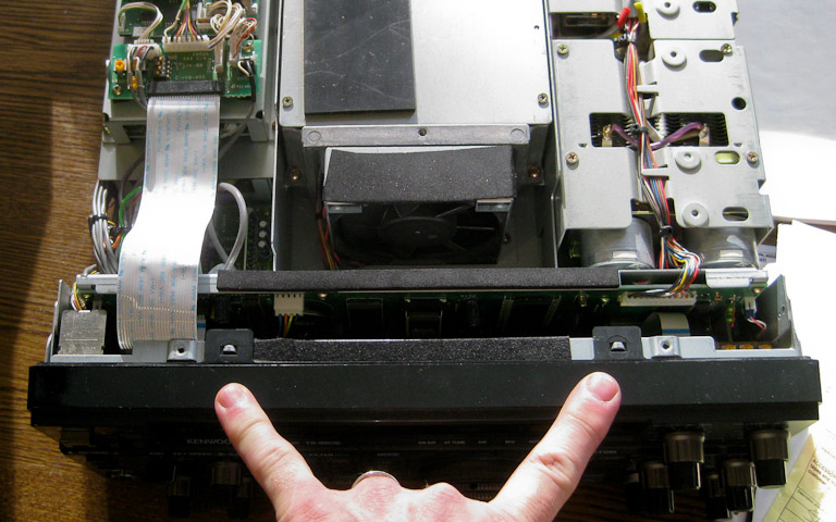
Install Top Cover
 The top cover must be installed first, because the bottom cover will overlap its screw holes.
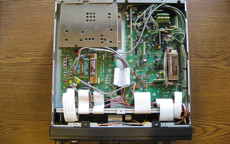
Connect to internal speaker (gray wire) to the small PCB on the top of the transceiver as shown in the photo at left.
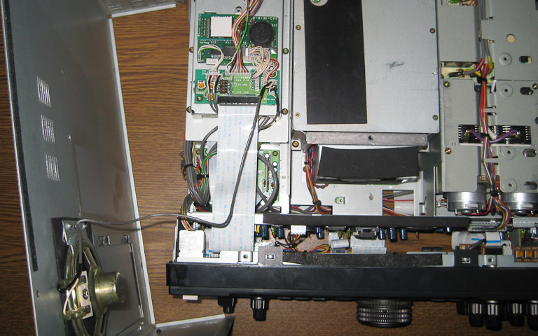 There are five screws on top of case, one near each corner plus one in the middle. You don't neeed
to remove the access cover plate or the speaker.
There are five screws on top of case, one near each corner plus one in the middle. You don't neeed
to remove the access cover plate or the speaker.
Install Bottom Cover
 Here is a gratuitous ham porn photo of the bottom of the TS-850s. :-)
Install the bottom cover last.
You don't need to remove the feet since they only anchor to the case and not to the frame underneath. You don't need to remove the bottom access cover.
If you took off the feet, notice that 2 are keyed (front) and 2 are flat (back). Rotate them into alignment before screwing them on.
There are five screws on bottom of case (apprx four corners plus middle front) plus three screws on left side and three more screws on the right side.
The side screws engage both top and bottom covers; this is why the bottom is the first cover off and the last one on.
| < Previous | Page 8 of 9 | Next > |
©1998-2024 Barry Hansen