Magnetic Levitation
Levitation
- Introduction
- Why
- Other Maglev
- Hard Drive Maglev
- Schematic
- Parts List
- Buying Parts
- Woodworking
- Other's
- Photographs
- Infrared Emitter
- Photodetector
- Reference Det
- Difference Amp
- Feedback Loop
- Loop Equations
- Bode Plot
- Phase Lead
- Output Amp
- Coil Driver
- PWM
- Lifting Coil
- PSPICE
- Build Time
- PCB
- Power Supplies
- Setup
- Test Power
- Test IR Emitter
- Test Signal Det
- Test Ref Det
- Adjust Sensing Res
- Test Diff Amp
- Test Non-Invert Amp
- Test Coil Driver
- Test Lifting Coil
- Results
Designing the Levitator Coil Driver
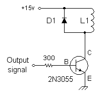
This circuit controls the current in the electromagnetic levitation coil L1. It is driven by a 741 op-amp, which is spec'd to source up to 40 mA of current. For any 2N3055 transistor with a beta = 50 or higher, it is sufficient for loads up to 2 amperes with no additional circuitry.
The base resistor provides some protection. It limits the output current demand on the op-amp. What is the actual limit? At worst case, the op-amp is at 15v and the base terminal is at 0.7v. So the maximum base current will be Ib = (15 - 0.7) / 300 = 48 mA.
Diode D1 protects the transistor. It is arranged to block the +12v from pin C. Normally D1 is non-conducting and all the current (if any) will flow through the coil L1 and the transistor. But at the instant the transistor turns off, the current circulating in the coil has to be safely dissipated somewhere. So the diode D1 turns on for a millisecond and allows the current to safely be discharged as heat in the coil.
How did I really choose the base resistor? I tried gradually increasing values of resistors while measuring the coil current. At some value, the coil current began to be reduced, so I went back to the next smaller resistor.
The actual maximum value of base resistor you can use depends on the maximum collector current required, and the gain (beta) of the particualr power transistor in the circuit. The value is not really critical, as long as the power transistor can run enough current through the coil. Indeed, you could probably leave out this resistor and connect the base directly to the op-amp output pin. You can experiment here, or just choose a safe value around 220 or 300 ohms.
| < Previous | Page 20 of 37 | Next > |
©1998-2024 Barry Hansen

