Magnetic Levitation
Levitation
- Introduction
- Why
- Other Maglev
- Hard Drive Maglev
- Schematic
- Parts List
- Buying Parts
- Woodworking
- Other's
- Photographs
- Infrared Emitter
- Photodetector
- Reference Det
- Difference Amp
- Feedback Loop
- Loop Equations
- Bode Plot
- Phase Lead
- Output Amp
- Coil Driver
- PWM
- Lifting Coil
- PSPICE
- Build Time
- PCB
- Power Supplies
- Setup
- Test Power
- Test IR Emitter
- Test Signal Det
- Test Ref Det
- Adjust Sensing Res
- Test Diff Amp
- Test Non-Invert Amp
- Test Coil Driver
- Test Lifting Coil
- Results
Designing the Output Amplifier
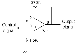
This circuit amplifies the control signal in preparation for the power output transistor. Why do we need this stage at all? Because we reduced the whole signal by one-ninth in the speed-plus-position circuit.

- This op-amp amplifies the control signal to provide plenty of "punch" to the power transistor and coil.
- And it isolates the rather large load of the power transistor from the capacitor's time constant and from the resistor divider bridge.
This 741 op-amp is wired as a standard non-inverting amplifier. The gain is computed from the
feedback and input resistors:
Gain = (Rf + Ri) / Ri = (370K + 1.5K) / 1.5K = 247
That's a lot of gain! Do we really need that much? I'm not sure, but it worked for me! <grin> Actually, with this much gain it acts more like a binary on-off switch than a linear amplifier. It will pretty much ensure the coil is either fully "on" or completely "off". Which is a good idea for reducing power dissipation in the final output transistor. So you probably don't need a very big heat sink for your power output transistor. You might experiment with lower values of gain to see what happens.
| < Previous | Page 19 of 37 | Next > |
©1998-2024 Barry Hansen