Barry's Coilguns
Mark 1
- Introduction
- Photos
- Launch Speed
- Oscillator
- Coil Timer
- Trigger Logic
- Coil Driver
- Power Supply
- Winding Coils
- Tube Size
- Projectile
- Breadboard
- Measuring Coil
- Max Coil Strength
- Computing Coil Timing
- Mark 1 Results
Coil Timer
How can you turn on each coil at the right time? How can you turn them off? How can you make it easy to experiment with other on/off times?
Time Counter
This coil gun design uses on/off times that are rather arbitrary. Well, not chosen at random, but the times are calculated in the spreadsheet according to the basic equations of motion. The coils do not turn on/off at identical intervals. The first coil is on for the longest period because the projectile is moving the slowest. It is moving much faster through the last coil, so it's on for the shortest period.
 We
need a circuit to measure out small period of time. It should be easy to change so we can try
different timing variations for the best performance. In short, we need switches (not jumpers)
to select the start-time and stop-time for each coil.
We
need a circuit to measure out small period of time. It should be easy to change so we can try
different timing variations for the best performance. In short, we need switches (not jumpers)
to select the start-time and stop-time for each coil.
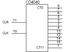
The clock circuit generates a steady stream of pulses. A simple 8-bit binary counter chip will count the pulses one-by-one. Its output is a regular 8-bit binary number, which divides the clock pulses into 256 time intervals. (Or less, if we reset the counter before it reaches maximum count.)
Time Decoder
This 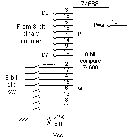 circuit
provides a simple method of decoding any particular count in the counter's range. The 8-bit comparator
chip comes in a 20-pin package.
circuit
provides a simple method of decoding any particular count in the counter's range. The 8-bit comparator
chip comes in a 20-pin package.
The switch is a standard 8-bit dip (dual in-line package) switch in a 16-pin package.
Each line needs a small pull-up resistor to ensure it stays high (a logic-1) when the switch is open. The pull-ups also provide noise immunity from unterminated inputs. The pull-ups come in a sip (single in-line package) for 8, 9 or 10 resistors at a time, with one pin tied to Vcc.
The output of the 8-bit comparator goes to a latch. The comparator's output remains high (logic 1) for only one clock cycle. The latch stays high until another comparator turns it off. You can use several of these coil timer decoders to provide all the necessary timing for the latches.
Using a counter resolution of 256 gives very good control. Each count is 1/256th of the total, or 0.4% accuracy.
Coil Timer
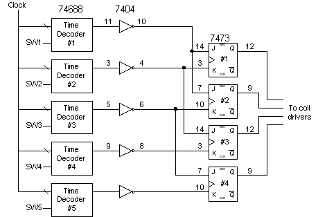
Each coil latch takes two time decoders: one time decoder turns it on, and one time decoder turns it off. So four coils would need at most eight decoder circuits.
However, usually one coil turns off at the exact time another turns on. So you only need one more time decoder than coils. My prototype uses three coils, so I used four time decoders. An extra time decoder is shown in the figure below, to show how additional decoders could be added.
 My
design always energizes two coils together (to keep the projectile in the "sweet spot").
It begins by turning on the first two coils. Then it turns off coil 1 while it turns on coil
3, leaving coil 2 and 3 on together.
My
design always energizes two coils together (to keep the projectile in the "sweet spot").
It begins by turning on the first two coils. Then it turns off coil 1 while it turns on coil
3, leaving coil 2 and 3 on together.
The four output lines connect to the high-power coil drivers.
The JK flip flops control the coils. The J input turns on the latch, and the K input turns it off again. Not shown for simplicity, is their clock input lines, which are connected to the high speed free-running clock oscillator.
The 7473 chip is obsolete, but that's what I had in the junk box. Any J-K flip-flop (with Clear) will work nicely.
The Reset line to each latch is also not shown. It should be connected to the reset signal from the trigger. This will hold them in a known good state before the first firing after power-up.
| < Previous | Page 5 of 16 | Next > |
©1998-2024 Barry Hansen