Barry's Coilguns
Mark 2
- Introduction
- Hints and Suggestions
- RLC Simulation
- RLC Analysis
- LC Time Sim
- Inductor Sim
- Wire Loop
- Java
- Photographs
- Schematic
- SCR
- Construction
- Result: Position
- Result: Turns
- Result: Length
- Result: Iron
- Result: Tube
- Result: Voltage
Coilgun Mark II Photos
What on earth does a coilgun look like? How did I build the Mark II coilgun? How are the coilgun parts arranged?
Overview
Here are some overall coilgun shots (pun intended!).

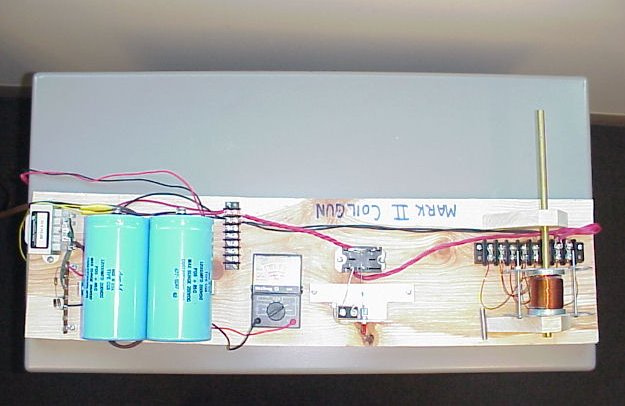
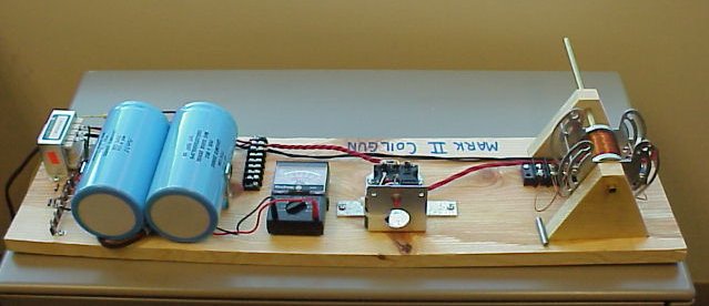
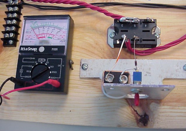
The small power transformer is next to two large blue capacitors at one end. The cheap black VOM monitors the charging level. A spring-loaded switch is mounted on a small bracket with a 9v battery to fire the "silicon power cube" SCR. The coil is aimed at a 5-gallon plastic bucket about five feet away.
Power Supply
These photos show closeup views of the power supply.
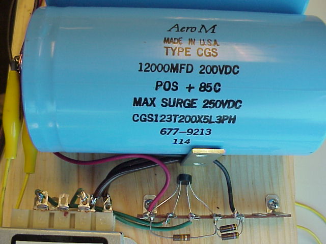

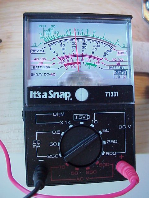
The transformer is fed by a brown line cord from 110vac. This connection is at the bottom of the transformer, and I've tried to keep this connection as far as possible from fingers. Two green wires from the top of the transformer carry the transformer output to the bridge rectifier on a terminal strip. The pair of parallel resistors limits the current to charge the capacitor. The single resistor will slowly and safely discharge the capacitor after power is removed. A cheap voltmeter ($7) monitors the capacitor's charge.
SCR and Trigger
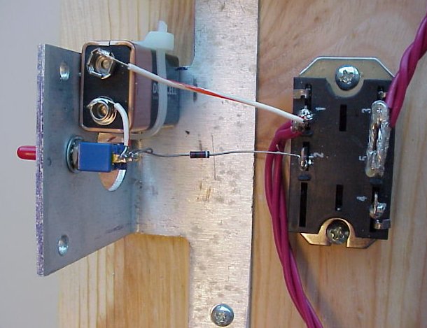
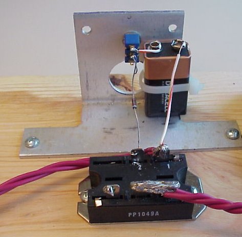
The black "silicon power cube" SCR is bolted down with its gate and drain toward the trigger circuit. A spring-loaded pushbutton switch will connect the 9v transistor radio battery through a small resistor to fire the SCR. The battery and switch are mounted on a bracket which held a small fan in a previous lifetime.
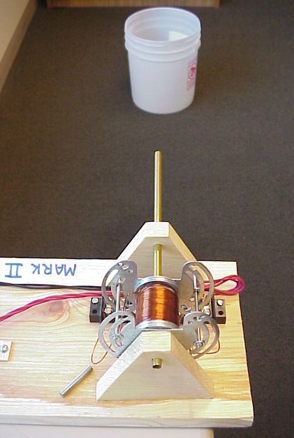
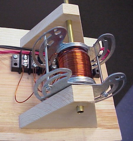
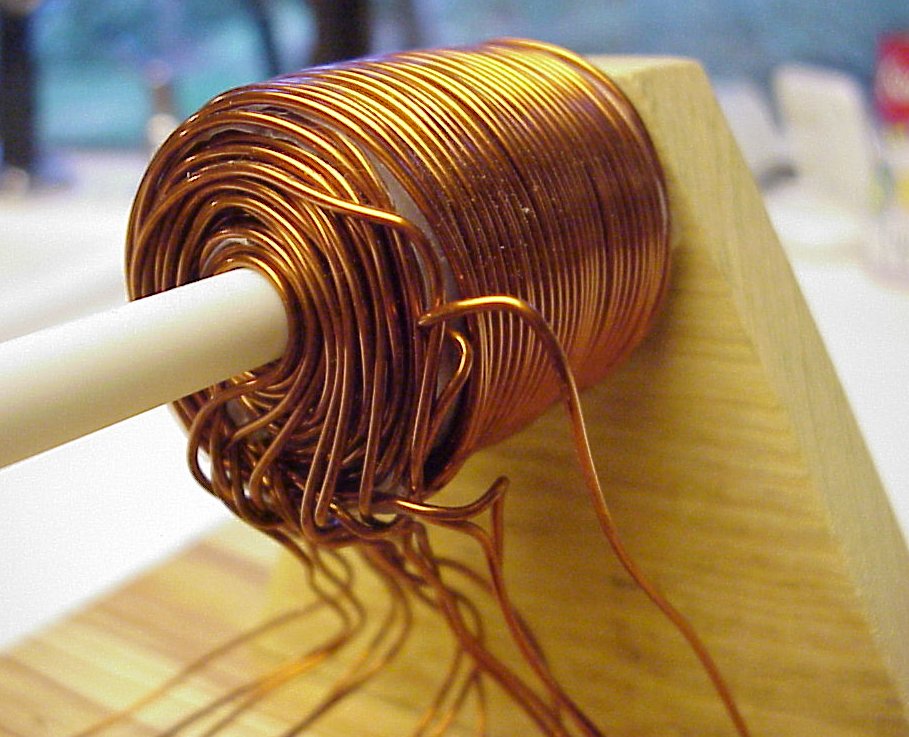
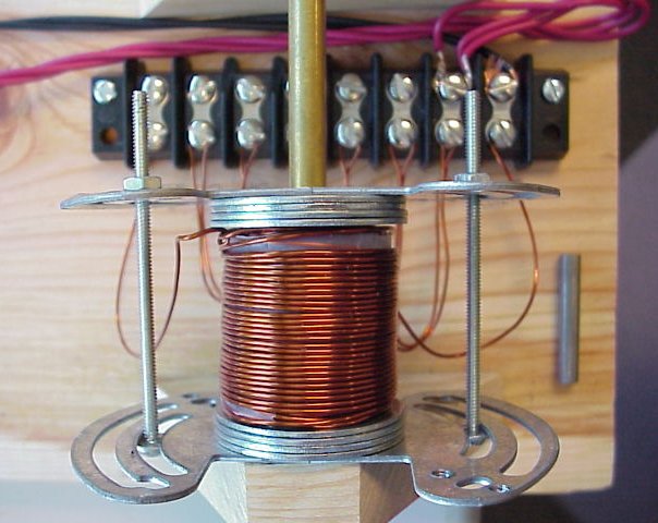
Coil and Projectile
The coil is held in mechanical compression to keep the windings from falling off or moving.
A bracket from a ceiling light fixture holds it together. Four steel washers at each end help
direct the magnetism in toward the tube.
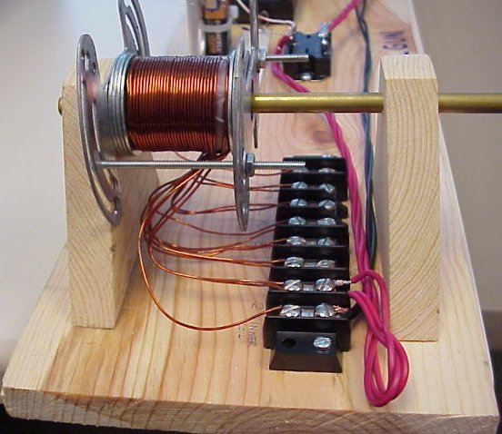
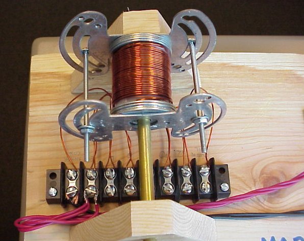
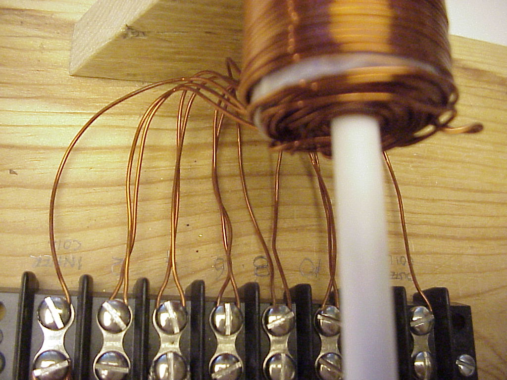
The coil is tapped every other layer, and the taps are sanded clean and screwed into an eight
position terminal strip (at $20 the most expensive component in the circuit!). The black wire
is ground, and the red wire is connected to various taps to tune the circuit.
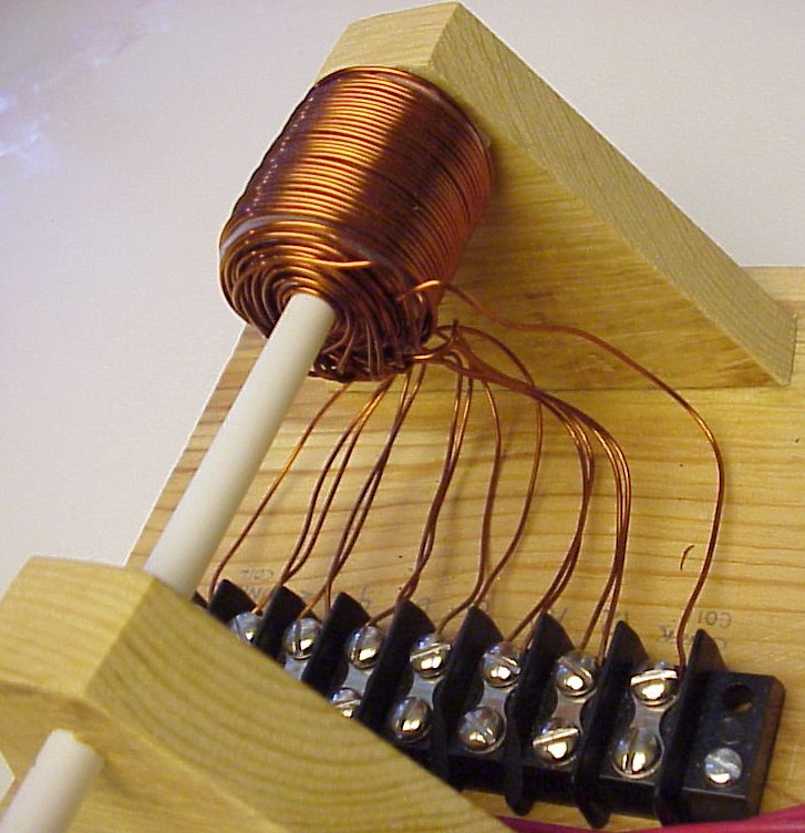

 The
projectile (a short steel rod) is laying on the board below the coil (see photo at right). It
is the same length as the length of the windings between the washers.
The
projectile (a short steel rod) is laying on the board below the coil (see photo at right). It
is the same length as the length of the windings between the washers.
This coilgun works best when only two layers of windings are used. Next time I can save a lot of winding! I should also use thicker wire to have lower inductance. This will be essential as I move to higher voltages with correspondingly faster speeds and shorting timing.
| < Previous | Page 9 of 18 | Next > |
©1998-2024 Barry Hansen