Practical Coilgun Design
Theory
- Introduction
- Number of Turns
- Magnet Wire
- Coil Size
- Wire Size
- External Iron
- Wire Loop
- Control
- Phototransistors
- Coil Length
- Number of Coils
External Iron
How can we increase the magnetic field strength by adding external iron? How much will it be increased?
My apologies for a very long web page -- there's a lot of material to cover! This page has enough detail that most people with advanced mathematics can verify my work.
Adding Washers and Pipe
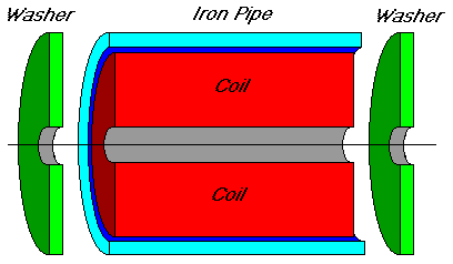 Suppose
we take our air coil and put iron in the flux return path around the coil. Adding iron increases
the total magnetic flux, by adding its magnetization to the field. The iron also guides the flux
toward the firing tube, where it is much closer to the projectile.
Adding external iron is cheap and easy to do. Just add a flatwasher or two onto each end, and enclose the coil in an iron pipe. An exploded view (how appropriate for a coilgun!) is shown here, cut in half to show the interior.
Note this is not very good for heat dissipation. It's going to take longer for the assembly to cool off after each shot. You might not want to do this if overheating is a problem. Also, this iron will saturate at very large values of magnetic flux.
Magnetic Field Lines
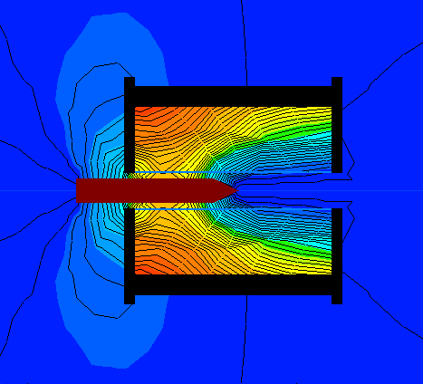 Here's
a flux diagram computed by QuickField. It illustrates how the external field is very small because
the iron carries most of the magnetization. The total magnetic flux is large because it is primarily
guided through the iron parts.
This is a cross-sectional view of the coil surrounded by iron. The dark red object in the middle is the projectile. The black parts are the iron. The thin black lines indicate the flux lines, while the color shows the flux density.
The washers are shown with a slightly larger outside diameter than the pipe. The washers are part of the black area at the left and right ends of the coil. They are larger than the pipe because, in an effort to get a very tight fit, we will squeeze sections of pipe between washers. An external clamp (not shown) will ensure they remain tight. Remember, any air gap is our enemy and should be minimized!
You might make note: the thing that makes the projectile move is the flux lines want to be as short as possible. Look at the lines going into the head and coming out near the tip of the projectile. These represent mechanical tension, pulling the projectile into the middle!
Computing Reluctance in Magnetic Circuit
This can be modelled as a magnetic circuit. A magnetic circuit is very similar to an electric
circuit:
The equivalent to resistance is reluctance, R, in "rels".
The equivalent to current is flux, F, in "lines per square
inch".
The equivalent to voltage is mmf or magnetomotive force, M,
in "amp-turns".
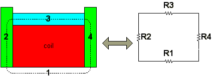
For electric circuits: current = voltage / resistance.
For magnetic circuits: flux = mmf / reluctance.
The total magnetic energy divides between iron and the gap in proportion to their reluctances. Because the relative permeability for iron is so large, most of the magnetic energy is stored in the air gap, even though the volume of air is relatively small.
The reluctance of a magnetic path is:
- increased as the length of the path is increased
- increased as the cross-sectional area is decreased
- increased as the reluctivity of the material in the path is increased
Therefore we can define the reluctance R as:
reluctance R = (path length) / (cross-sectional area * permeability)
Goal: Let's use this to calculate the approximate total reluctance of the entire magnetic path. We'll use variable names to represent the physical dimensions, and so end up with equations in terms of real measurable dimensions. From this, and the total desired flux, we can calculate the necessary thickness of iron, and understand what factors limit performance.
Rtotal = R(air core) + R(left flat washer) + R(pipe) + R(right flat washer)
Rtotal = R1 + R2 + R3 + R4
R1: Finding Reluctance of Air Core
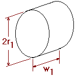 Remember
the general definition of reluctance? Here's how reluctance was defined in the first place:
![]()
Now let's figure out how it applies here. For a cylinder of air, let's name r1 = inside radius of coil and w1 = width of coil. Note this is but a convenient approximation, really the flux takes a path a little longer than the physical width of the coil.
The cross-sectional area of a circle is πr2. The relative permeability of air = 1, so the absolute permeability here is just µ0. If we substitute these names into the equation, the final answer for reluctance of this portion is:

R2,R4: Finding Reluctance of Flat Washer
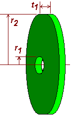 This
shape is trickier. The flux enters all along the outside edge, and travels radially toward the
center. It exits all along the smaller inside opening in the washer.
We'll name the inside washer radius the same as the air core above, r1. We'll name the outside washer radius as r2. The thickness of the washer is t1.
The cross-sectional area on the outer rim is rather large, it is the surface area of the rim itself. A = 2 πr2t1.
The cross-sectional area decreases smoothly as the ring of flux travels to the middle of the washer. The area is small on the inner hole. A = 2 µr1t1.
But what happens in between the outer and inner rims? To calculate the net reluctance across the washer, we need to sum up each infinitesmal ring separately, as the rings progressively get smaller. The reluctance is the sum of an infinite series of infinitely thin rings mounted one inside another. Calculus is the perfect tool, and these steps show how it is used from the initial problem statement to solution:
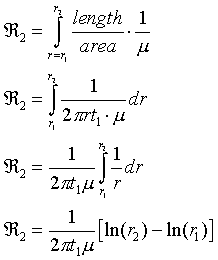
Notice that subtracting logs is the same as dividing their arguments, so here's the final answer. It shows the reluctance is inversely proportional the the washer thickness, and it increases as the inner hole gets smaller. Again this is obviously only an approximation; as the inner hole radius approaches zero the reluctance is not infinite, instead the flux escapes from the sides of the washer which we aren'tt taking into account.

R3: Finding Reluctance of Pipe
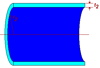 The
cross-sectional area of the pipe is the area of a thin doughnut shaped wafer around the outside.
Its inner radius is r2 and its outer radius is r2+t2.
So its area is the difference between an outer circle and what's removed from the middle, along
with a few steps of algebra for simplifying the equation:

Now we have the cross-sectional area, we compute the pipe's reluctance from the usual definition. We substitute in the area from the equation above:

Finding Total Reluctance, R1+R2+R3+R4
Combining the parts from the sections above, we obtain:
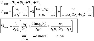
Results and Conclusions
Well, this looks complicated, but here's how to use it. Presumably you have already designed and built the coil. You know its physical dimensions of r1, r2 and w1. Now all you need to know is what thickness of washers t1 and pipe t2 to choose.
You want to find the thickness of external iron such that its reluctance terms are small compared to the air core's. This usually means that it is less than 10%. So go ahead: calculate the term for the air core. Then try different values of thickness such that the washers and pipe result in 10% or less reluctance than the air core.
You will probably find that pretty much no matter what reasonable washer and pipe thicknesses you choose, the total path's reluctance is governed by the air core. The term of 1/ur helps make the other terms so small because the relative permeability ur is typically around 2,000 to 5,000.
| < Previous | Page 6 of 11 | Next > |
©1998-2024 Barry Hansen