Barry's Coilguns
Mark 1
- Introduction
- Photos
- Launch Speed
- Oscillator
- Coil Timer
- Trigger Logic
- Coil Driver
- Power Supply
- Winding Coils
- Tube Size
- Projectile
- Breadboard
- Measuring Coil
- Max Coil Strength
- Computing Coil Timing
- Mark 1 Results
Breadboard for Timing Electronics
How do you build the electronics for timing, counting and comparing? How can you make it easy to modify? What did I build, and how did I arrange things?
Breadboarding Electronics
The easiest breadboard to use for IC's is the push-down pin array. You just press the hookup wire into the holes, and each group of five holes in a row are connected underneath. It's sold (at a rather high price) by Radio Shack and (at better prices) other places.
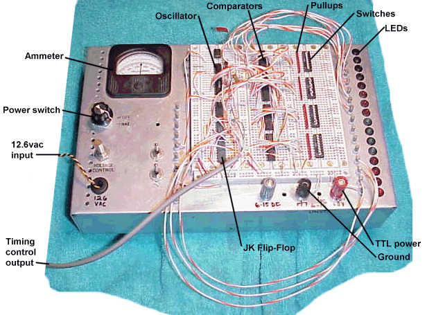
My breadboard is mounted on an aluminum box that also carries a 5v supply for TTL. It has sixteen LEDs with Darlington drivers along the right-hand side for debugging logic circuits.
Breadboard Photo

Breadboard Wiring
There are three sections of breadboard side-by-side, with longer thin strips for power distribution along the bottom.
The long gray cable for "timing control output" goes to the business end of the coilgun. It is an eight-wire cat-3 cable leftover from some telephone re-wiring at home. It has color-coded wire assignments of:
| green/white | coil #1 |
| blue/white | coil #2 |
| orange/white | coil #3 |
| brown/white | (spare) |
| white/orange | trigger |
| white/blue | trigger |
| white/brown | ground |
| white/green | ground |
Comparator Wiring
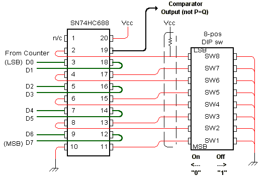
There are three 8-bit comparators, each wired to a pull-up resistor block and an 8-bit DIP
switch. The wiring gets a little messy in this area, with all the 8-bit buses running around.
So here's a diagram showing the pin connections between the chips, and notes about which switch
does what. All four comparators are wired like this. 
Note the switch is labeled SW8 = LSB, because the engraving on my switch block says '8' but the wiring is connected to D0 which is the least significant bit of the counter.
Note the switch says On = "0", because again the engraving on my switch block says "On" but the wiring corresponds to a logic 0. Sorry if it's confusing, but it seemed easier at the time to orient the switch this way. I trust you will find a more sensible way than I did for this portion!
| < Previous | Page 12 of 16 | Next > |
©1998-2026 Barry Hansen