Barry's Coilguns
Mark 1
- Introduction
- Photos
- Launch Speed
- Oscillator
- Coil Timer
- Trigger Logic
- Coil Driver
- Power Supply
- Winding Coils
- Tube Size
- Projectile
- Breadboard
- Measuring Coil
- Max Coil Strength
- Computing Coil Timing
- Mark 1 Results
Coil Driver
How do you energize a coil? How can you mix 5-volt TTL with higher-voltage coils? How can you provide some protection to the rest of the circuits in case of output transistor failure?
High Power Coil Driver
Okay, this isn't really high power, but it certainly illustrates the design considerations. Some of the ideas are borrowed from solenoid drivers in commercial pinball machines, so nicely documented at www.randyfromm.com/solenoid.htm. (It's now gone, but thanks anyway, Randy!)
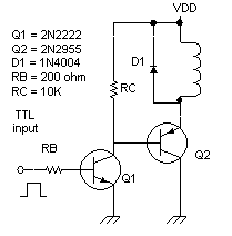
The general idea is to use a high-current pnp transistor (Q2 = 2N2955), to bring the bottom
end of the coil to near ground. The other end of the coil is attached to the high-power driver,
 VDD = +15 vdc. When Q2 is
turned on, it goes into saturation. That means there's only 0.2v between its collector and emitter.
So how much current goes through the coil? One end is at +15 vdc, and the other is at 0.2 volts. So the current through a 5-ohm coil will be the voltage v divided by resistance r, or (15 - 0.2)/5 or almost 3 amps. For a comfortable design margin, let's assume we need to drive Q2 fully on with at least 5 amps output current capability. This will let us swap in a heavier coil someday without redesigning this stage.
The base current required to turn on a 2N2955 is the final current divided by the transistor gain B (beta). Assuming minimum beta B of 20, the necessary Q2 base current is 5/20 = 0.25 amps base current. That's a lot more than your typical JK flip-flop can provide. So we'll use another transistor, Q1, to drive the 2N2955. Let's use a garden variety npn transistor, the reliable workhorse 2N2222, wired in a Darlington pair configuration. We want to drive both transistors deep into saturation for maximum current handling and minimum collector-emitter voltage drop.
The base current required to turn on the 2N2222 will be its output current divided by its gain B (beta). Assuming its gain is at a minimum B = 25, then its base current must be at least 250mA/25 = 10 mA. This is easily provided by a TTL chip such as a JK flip flop. (Careful of which family you use; the low-power LS family 74LS73 can't source much current.)
We should protect the transistors from the coil's kickback voltage. When its magnetic field collapses as the output transistor turns off, a high voltage spike is generated. This can easily overcome a transistor's maximum breakdown voltage. So we provide a protection diode across each coil, which passes current to keep its forward voltage drop down to about 0.7v.
The 2N2222 configuration also provides another piece of protection for the sensitive TTL logic. A typical failure mode of output transistors is to short the collector to the base. With this 2N2222, the fragile TTL output is protected by the collector-base junction of Q1. The typical reverse breakdown voltage of a 2N2222 is 60 volts or more, so it provides ample protection for this application. However, if you plan to raise VDD above 60 volts, you should replace both Q1 and Q2 with transistors that have a higher c-e reverse breakdown voltage.
Calculating Base Input Resistor
What value resistor RB should be chosen to limit the current through Q1? It really provides the base current IB to the 2N3055. So its resistance is its voltage drop divided by the base current of Q1. Assume a TTL chip output high is 2.4v, and two forward-biased B-E junctions are 0.4v. Note the Q1 base current is the coil current divided by both transistors' gain.
RB = (2.4v - 0.4v) / IB
RB = 2.0v / (IB / B / B)
RB = 2 B2 / ICoil
Let's solve with our values. Assuming coil current is 5A, and minimum transistor gain is 25, we get RB = 250 ohms. A common value is 220 ohms, so that's what I used.
| < Previous | Page 7 of 16 | Next > |
©1998-2026 Barry Hansen