Barry's Coilguns
Mark 4
- Introduction
- Objectives
- Schematic
- Projectiles
- Capacitor
- Kinetic Energy
- Timing
- Coil Design
- SCR
- Diode
- Damping Resis
- Bleeder Resis
- Iron Type
- Iron Shape
- Iron Size
- Low Voltage
- High Voltage
- Isolation
- Low Voltage Power
- Charging Resis
- Construction
- Firing Tube
- Retention Bolt
- SCR Wiring
- Transformer
- External Iron
- Purchases
- Speed Measurement
- Results
- Coil of 97 Turns
- Coil of 84 Turns
- Damping Resistor
- Burned Coil #1
- Coil of 56 Turns
- Eddy Currents
- Starting Position
- Conclusions
Charging Resistor
It is desirable to limit the charging current to avoid overheating or damaging components. How do we go about choosing an appropriate value?
Charging Resistor
 There
are inherent current limits on a mains-connected power supply. The power supply impedance comes
in part from the internal resistance of its components. The transformer also limits current because
all power is transferred magnetically through the iron core. The core’s cross-section and
material dictates the maximum secondary current.
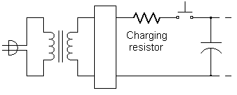
The purpose of the series charging resistor is to limit surge current, but not so much that charging time becomes excessive.
The charging time is governed by the RC time constant. We will assume the capacitor is sufficiently charged in 5RC time constants. Our self-imposed requirement is a charging time under 10 seconds, so let's begin with a goal of being fully charged in 5 seconds or less.
Since the power supply impedence is a significant part of the total series charging resistance, our choice depends on the implementation.
Variac Power Supply
The Variac is capable of providing very large currents (6 amps or more), so a charging resistor is required to limit current. The calculations are:
5t = 5 seconds
T = 1 second
![]()
Based on this calculation, we started with a 50-ohm series resistor. Some experimentation found that a 25-ohm rated at 25W worked well, remained cool, and provided full charge in five seconds or less.
Isolation Transformer Power Supply
The isolation transformer in the fixed-voltage supply was selected to be of the proper size to limit charging current. See Isolation Transformer to see how this was done. No current-limiting resistor is needed when the transformer is of appropriate size.
| < Previous | Page 20 of 37 | Next > |
©1998-2026 Barry Hansen