Barry's Coilguns
Mark 4
- Introduction
- Objectives
- Schematic
- Projectiles
- Capacitor
- Kinetic Energy
- Timing
- Coil Design
- SCR
- Diode
- Damping Resis
- Bleeder Resis
- Iron Type
- Iron Shape
- Iron Size
- Low Voltage
- High Voltage
- Isolation
- Low Voltage Power
- Charging Resis
- Construction
- Firing Tube
- Retention Bolt
- SCR Wiring
- Transformer
- External Iron
- Purchases
- Speed Measurement
- Results
- Coil of 97 Turns
- Coil of 84 Turns
- Damping Resistor
- Burned Coil #1
- Coil of 56 Turns
- Eddy Currents
- Starting Position
- Conclusions
Coil of 97 Turns
This was the first and largest of the coils tested.
Yes, I realize all these numbers and calculations are boring, but this engineering notebook includes all my raw data to permit an independent check of the calculations and conclusions later.
Coil of 97 Turns
See the Projectiles page for details of these projectiles.
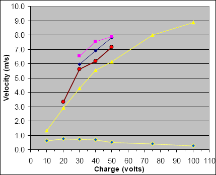
MeasurementsThe raw measurements are shown in red in the table below, using horizontal ballistics measurements. |
|||||
Projectile: |
A |
C |
D |
F |
|
|---|---|---|---|---|---|
| Length: | 3.5" | 2.5" | 2" | 1.5" | |
| Mass: | 4.301 g | 2.163 g | 1.464 g | 0.7345 g | |
Potential energy (joules) |
Charge (volts) |
Horiz
Distance (inches) |
Horiz
Distance (inches) |
Horiz
Distance (inches) |
Horiz
Distance (inches) |
| 0.6 J | 10 v | 23" | - | - | - |
| 2.4 | 20 | 51 | 58 | - | - |
| 5.4 | 30 | 75 | 98 | 104 | 114 |
| 9.6 | 40 | 97 | 108 | 121 | 132 |
| 15.0 | 50 | 107 | 125 | 137 | 138 |
| 33.8 | 75 | 140 | - | - | - |
| 60.0 | 100 | 155 | - | - | - |
VelocityUsing the equations for horizontal ballistics and the raw data, the velocity is calculated for each of the measurements above. The computed velocity is shown in red. |
|||||
Projectile: |
A |
C |
D |
F |
|
Potential energy (joules) |
Charge (volts) |
Velocity (m/s) |
Velocity (m/s) |
Velocity (m/s) |
Velocity (m/s) |
| 0.6 J | 10 v | 1.316 | - | - | - |
| 2.4 | 20 | 2.919 | 3.319 | - | - |
5.4 |
30 | 4.292 | 5.609 | 5.952 | 6.524 |
| 9.6 | 40 | 5.551 | 6.181 | 6.925 | 7.554 |
| 15.0 | 50 | 6.124 | 7.154 | 7.840 | 7.898 |
| 33.8 | 75 | 8.012 | - | - | - |
| 60.0 | 100 | 8.871 | - | - | - |
EfficiencyCalculate efficiency as shown in red. |
|||||
Projectile: |
A |
C |
D |
F |
|
Potential energy (joules) |
Charge (volts) |
Efficiency (%) |
Efficiency (%) |
Efficiency (%) |
Efficiency (%) |
| 0.6 J | 10 v | 0.6 % | - | - | - |
| 2.4 | 20 | 0.8 | 0.5 | - | - |
| 5.4 | 30 | 0.7 | 0.6 | 0.5 | 0.3 |
| 9.6 | 40 | 0.7 | 0.4 | 0.4 | 0.2 |
| 15.0 | 50 | 0.5 | 0.4 | 0.3 | 0.2 |
| 33.8 | 75 | 0.4 | - | - | - |
| 60.0 | 100 | 0.3 | - | - | - |
Graphical Results
Coil Analysis
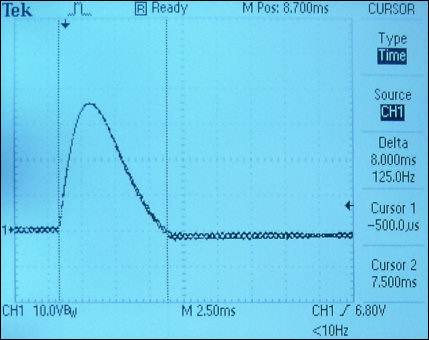
This coil with 97 turns measured 8 ms half-cycle waveform. The image below indicates peak currents of 350 A at 100v charge.
How Does This Coil Need to Change?
The speeds and efficiencies are very low. We need to shorten the time and increase the peak current.
From the oscilloscope, the half-cycle time is 8 ms, and we desire our next coil to be 25% faster, which means a 6 ms discharge time.
Using a Java RLC simulator, we find the estimated inductance is L = 525 uH for an 8 ms discharge with a 12,000 uF capacitor.
To reduce this to 6 ms, a Java LC Time Simulator finds that inductance should be reduced to a value of 304 uH.
We don’t want to model an iron-core coil in FEM to derive the inductance, so let’s apply the same ratio change to an air-core model. This is much easier to do, and the next bench test will tell us if this method is accurate.
- We need to reduce inductance L by a factor of (304 uH) / (525 uH) = 0.5790
- The 97-turn coil in air has inductance L = 186 uH, according to a Java Inductor Sim (using 12 AWG, ID=6mm, OD=69mm, length=16mm).
- The new coil in air should have L = (186 uH) * (0.5790) = 107.7 uH
- Using the Java Inductor Sim again, we find an 84-turn coil will have the desired inductance.
- Therefore, removing 13 turns should result in the desired 6 ms discharge time.
| < Previous | Page 30 of 37 | Next > |
©1998-2026 Barry Hansen