Barry's Coilguns
Mark 4
- Introduction
- Objectives
- Schematic
- Projectiles
- Capacitor
- Kinetic Energy
- Timing
- Coil Design
- SCR
- Diode
- Damping Resis
- Bleeder Resis
- Iron Type
- Iron Shape
- Iron Size
- Low Voltage
- High Voltage
- Isolation
- Low Voltage Power
- Charging Resis
- Construction
- Firing Tube
- Retention Bolt
- SCR Wiring
- Transformer
- External Iron
- Purchases
- Speed Measurement
- Results
- Coil of 97 Turns
- Coil of 84 Turns
- Damping Resistor
- Burned Coil #1
- Coil of 56 Turns
- Eddy Currents
- Starting Position
- Conclusions
Coil Design
The coil design is one of the most difficult and important parts of the coilgun.
The coil must simultaneously satisfy a number of conflicting requirements for inductance, resistance, maximum current and physical dimensions. To further complicate the analysis, the usage of external iron requires finite-element modeling (FEM) software to find force and inductance.
Coil
The approach used here is to choose coil dimensions to fit the space available in the largest available transformer core. Then measurements are taken as wire is progressively removed, tuning the coilgun for maximum speed within limitations of peak current.
The wire size is chosen from experience, which has always found that a few turns of heavy, thick wire is better than lots of turns of light, thin wire.
The coil’s physical dimensions are dictated by the space available:
- Coil length must fit into the transformer core.
- Inside diameter must fit snugly on the firing tube.
- Outside diameter should be large (to maximize turns/inch), but small enough to fit within the transformer core.
- Note that inductance (L) is proportional to N2 (square of turns), so plan on building a coil larger than needed and then remove turns during tuning.
- Coil resistance should be small – or at least no larger than the critical damping resistance.
 The
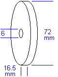
actual coil was constructed of 12 AWG wire (American wire gauge) of 2.0 mm diameter:
- 97 turns
- i.d. = 6 mm
- o.d. = 72 mm
- length = 16.5 mm
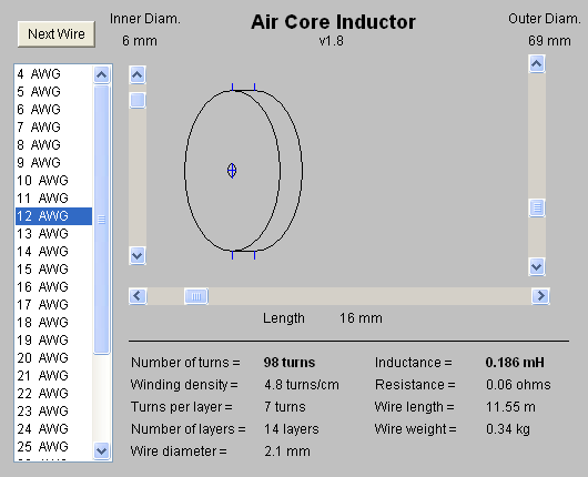
To check the construction and estimate its minimum inductance, we employed a Java coil simulator such as https://coilgun.info/mark2/inductorsim.htm :

| < Previous | Page 8 of 37 | Next > |
©1998-2026 Barry Hansen