Barry's Coilguns
Mark 4
- Introduction
- Objectives
- Schematic
- Projectiles
- Capacitor
- Kinetic Energy
- Timing
- Coil Design
- SCR
- Diode
- Damping Resis
- Bleeder Resis
- Iron Type
- Iron Shape
- Iron Size
- Low Voltage
- High Voltage
- Isolation
- Low Voltage Power
- Charging Resis
- Construction
- Firing Tube
- Retention Bolt
- SCR Wiring
- Transformer
- External Iron
- Purchases
- Speed Measurement
- Results
- Coil of 97 Turns
- Coil of 84 Turns
- Damping Resistor
- Burned Coil #1
- Coil of 56 Turns
- Eddy Currents
- Starting Position
- Conclusions
HV Isolation Transformer
Any device plugged in to the power mains should be isolated from direct connections by using a transformer. This provides safety from accidental contact, and limits the current in case of short-circuit conditions in the power supply.
The circuits shown below describe how an isolation transformer was selected to charge the HV capacitor.
Isolation Transformer
Although commercial “isolation transformer” exist and are readily available, several surplus transformers in like-new condition were at hand. We can achieve the same effect by connecting two identical transformers back-to-back, to obtain 110 vac. Note that this reduces the overall current capability compared to ratings, and so some testing is needed to confirm how they will operate.
Three transformer pairs were tested. Our goal is to charge the 12,000 TF capacitor in ten seconds or less.
The photo shows one each of the transformers; an identical set of transformers are available but not shown.
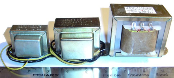
Each of the three transformer pairs were tested (see schematic and photo above) and their output measured. We recorded the voltage in loaded and unloaded conditions.
- T1 = T2 = 25.2 vac ct, 450 mA
Manufacturer: Radio Shack 273-1366A
No load: Vout = 116 vac
RL = 25 ohms: Vout = 10.1 vac
Current = I = E/R = (10.1v) / (25 ohms) = 404 mA
When connected to bridge rectifier and charging circuit we measured a charge rate of 30 sec to reach 150vdc, with no current-limiting resistor. This is much too slow.
- T1 = T2 = 12.6 vac ct, 3-amp
Manufacturer: Radio Shack 273-1511B
No load: Vout = 116 vac
RL = 25 ohms: Vout = 30.5 vac
Current = I = E/R = (30.5v) / (25 ohms) = 1.22 amp
When connected to bridge rectifier and charging circuit we measured a charge rate of 8 sec to reach 150vdc, with no current-limiting resistor. This almost meets requirements.
- T1 = T2 = 48 vac ct, 3-amp
Manufacturer: Unknown
No load: Vout = 120 vac
RL = 25 ohms: Vout = 64.7 vac
Current = I = E/R = (64.7v) / (25Y) = 2.588 amp
When connected to bridge rectifier and charging circuit we measured a charge rate of 3 sec to reach 150vdc, with no current-limiting resistor. This is quite good, and therefore this pair of transformers were chosen.
| < Previous | Page 18 of 37 | Next > |
©1998-2026 Barry Hansen