Practical Coilgun Design
Inductors
- Introduction
- Inductive Kickback
- Inductance
- Measure Inductance
- Damped Oscillator
- Critically Damped
Inductive Loads and Diode Protection
How do you protect against inductive kick-back?
Inductive Loads
What happens if you open a switch that is providing current to an inductor? Since inductors have the property V = L di/dt, it is not possible to turn off the current suddenly, since that would imply an infinite voltage across the inductor's terminals.
 What
happens instead is that the voltage across the inductor suddenly rises and keeps rising until
it forces current to flow. Electronic devices controlling inductive loads can be easily damaged,
especially the component that "breaks down" in order to satisfy the inductor's craving
for continuity of current.
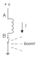
Consider the circuit shown at right. The switch is initially closed, and current I is flowing through the inductor. When the switch is opened, the inductor "tries" to keep current flowing from A to B, as it had been. That means that terminal B goes positive relative to terminal A. In a case like this it may go 1000 volts positive before the switch contact "blows over". This shortens the life of the switch and also generates impulsive interference that may affect other circuits nearby. If the switch happens to be a trasnsistor, it would be an understatement to say that its life is shortened; its life is ended!
Diode Protection
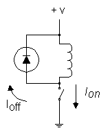
 The best solution is to put a diode across the inductor, as shown at left. The diode must be able
to handle the initial diode current, which equals the steady current that had been flowing through
the inductor; something like a 1N4004 is fine for many cases.
- When the switch is on, the diode is back-biased (from the dc drop across the inductor's winding resistance).
- At turn-off the diode goes into conduction, putting the switch terminal a diode drop above the positive supply voltage.
The only disadvantage of this protection circuit is that it lengthens the decay of current through the inductor, since the rate of change of inductor current is proportional to the voltage across it.
For applications where the current must decay quickly (high-speed impact printers, high-speed relays, etc.), it may be better to put a resistor across the inductor, choosing its value so that Vsupply + IR is less than the maximum allowed voltage across the switch. For fastest decay with a given maximum voltage, a zener could be used instead, giving a ramp-down of current rather than an exponential decay.
Source: "The Art of Electronics" by Horowitz and Hill, Cambridge University Press, copyright 1980, ISBN 0-521-23151-5
| < Previous | Page 2 of 6 | Next > |
©1998-2026 Barry Hansen