Practical Coilgun Design
Inductors
Inductors
What is an inductor? How do inductors behave?
Inductors
Inductors are closely related to capacitors; the rate of current change in an inductor depends on the voltage applied across it, whereas the rate of voltage change in a capacitor depends on the current through it. The symbol and defining equation for an inductor is

where L is called the inductance and is measured in henrys (or mH, uH, etc.) and "di/dt" is the change in current over a small period of time.
Putting a voltage across an inductor causes the current to rise as a ramp (for a capacitor, supplying a constant current causes the voltage to rise as a ramp; 1 volt across 1 henry produces a current that increases at 1 amp per second.
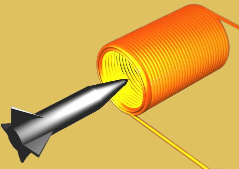
The symbol for an inductor looks like a coil of wire; that's because, in its simplest form, that's all it is. Variations include coils wound on various core materials, the most popular being iron (or iron alloys, laminations, or powder) and ferrite, a black, nonconductive, brittle magnetic mterial. These are all ploys to multiply the inductance of a given coil by the "permeability" of the core material. The core may be in the shape of a rod, a toroid (doughnut), or even more bizarre shapes, such as a "pot core" (which has to be seen to be understood).
Inductors find heavy use in radiofrequency (RF) circuits, serving as RF "chokes" and as parts of tuned circuits. A pair of closely coupled inductors form the interesting object known as a transformer.
An inductor is, in a real sense, the opposite of a capacitor.
Inductance and Reactance
Every conductor has inductance, even though the conductor may not have been designed as an inductor.
Inductance in any circuit is the property that opposes any change in the existing current. The unit of inductance may be stated in henrys, millihenrys, or microhenrys.
When an alternationg voltage is applied to an inductance, a back electromotive force (emf) is generated in the inductance. This emf is proportional to the rat at which the current changes -- The more rapid the change, the greater the back emf developed. And this, in turn, is proportional to the frequency of the alternating voltage.
This opposition to the flow of alternating current is called inductive reactance, symbolized by XL.
Reactance is measured in ohms, and the formula for inductive reactance is:
XL = 2 π f L
Example: The reactance of a 5.26-millihenry coil at 50 Hz is:
XL = 2 π f L = 6.2832 * 0.00526 * 50 = 1.65 ohms
| < Previous | Page 1 of 6 | Next > |
©1998-2026 Barry Hansen