Magnetic Levitation
Levitation from 1996 Electronics Now
- Introduction
- How It Works
- Schematic
- Parts list
- Construction
- Final assembly
- Operation
Finishing Construction - Electronics Now, Feb 1996
Final Assembly
 Because
the magnetic field from the coil loses strength rapidly with distance, it is important that the
center of the infrared beam formed by IRLED and IRDET be no more than 0.2 inches below the coil.
Otherwise, the coil will not be able to overcome the weight of the metal globe. this distance
was determined by experimentation using the specific components shown in the Parts
List. If you use a different coil or try to levitate objects of different weights, you will
have to experiment on your own to find the best beam position.
The aluminum bracket shown in Fig. 4 is a convenient mounting support for the coil and the reflective LED holders. The dimensions shown will ensure that the infrared beam is the correct distance below the coil. This bracket is available from the source shown in the parts list or you can use Fig. 4 to fabricate your own.
Figure 5 shows how to drill the top cover of the plastic enclosure to accept the aluminum bracket and provide mounting holes for S1, LED1 and R15.
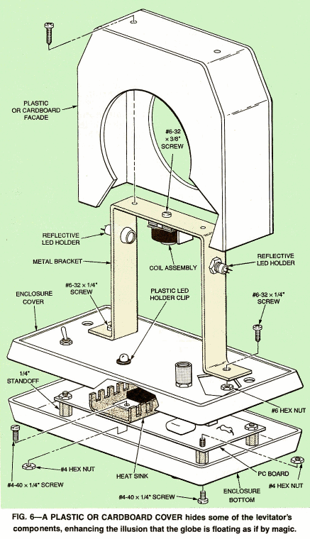
Figure 6 shows how everything fits together for the final assembly. Mount the PC board inside the enclosure bottom using 1/4 inch standoffs and the appropriate hardware. Next attach the metal bracket to the top of the enclosure with two No. 6-32 x 1/4 inch screws and nuts. Remove the nuts from the reflective LED holders and mount both of them as shown in the diagram. Then attach the coil assembly to the top of the bracket with another No. 6-32 screw. Lastly, push the plastic LED holder clip into the center hold of the cover as shown.
Feed the IRLED and its wires through the 1/4-inch hole in the top cover and insert the infrared LED into the reflective holder. Push the IRLED in until the rubber piece fits snugly. Repeat the process with Q6 on the other end. Next feed the coil wires from the PC board through the cover and solder them to the coil. Then mount S1, LED and R16 to the enclosure cover. Before putting the enclosure halves together, file a small notch in the back edge to allow the adapter's cord to exit. Attach the plastic knob to the potentiometer R16.
| < Previous | Page 6 of 7 | Next > |
©1998-2026 Barry Hansen