Magnetic Levitation
Levitation from 1996 Electronics Now
Schematic Diagram - Electronics Now, Feb 1996
Schematic

Circuit Details
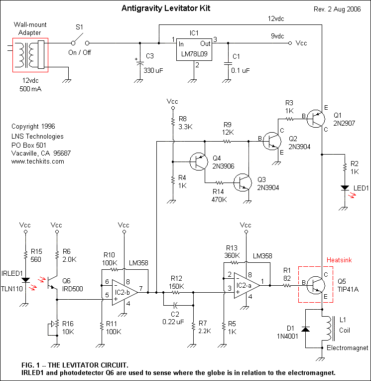
Figure 1 is the levitator's schematic. Power is supplied by a wall mounted AC/DC adapter with an output of 12 volt DC at 500 milliamperes. The electromagnet coil draws most of the current in this circuit, so it is powered directly from the 12-volt output of the power adapter. Stable voltage for the rest of the circuit is obtained by regulating the adapter's output to 9 volts with IC1, a LM78L09 voltage regulator that is capable of supplying up to 100 milliamperes of current. Capacitors C1 and C3 provide additional voltage filtering.
IRLED1 is an infrared light emitting diode, much like those used in infrared remote controls for consumer-electronics equipment. Resistor R2 limits the forward current to IRLED1 to about 15 milliamperes. The IRLED emits a constant, invisible beam whenever switch S1 is turned on. Phototransistor Q6 detects the infrared beam; it is wired with R6 and potentiometer R16 to convert the infrared beam into a DC voltage. Potentiometer R16 adjusts the output voltage of Q6, which is fed to pin 5 of IC2-b, one half of an LM358 operational amplifier.
The op-amp, which is configured for a gain of two, [(R11 + R10)/R11] buffer and amplifies the output of Q6. The output of IC2-b is fed to a second amplifier stage, IC2-a through C2 and R12. The output signal from IC2-a drives transistor Q5 to vary the current to the electromagnet coil. Because Q5 gets very warm during operation, it requires a good heat sink. Diode D1 protects Q5 from reverse voltage spikes from the coil.
Mylar capacitor C2 plays an important role in this circuit. It forms a differentiator with IC2-a. The capacitor blocks slow voltage changes, but passes any rapid changes in the input signal and allows them to be amplified by IC2-a. The slow voltage changes are attenuated by R12 and R7 before being amplified by IC2-a.
The purpose of this part of the circuit is to perform closed-loop control using a combination of proportional and derivative modes. Both modes are needed to insure that the levitation is stable.
Ther est of the circuit functions as a voltage-level detector that uses Q1 to switch the 12-volts to Q5 on or off. The level detector keeps the electromagnet powered off when there is no object in the beam. This is to prevent overheating of the coil. The level detector also turns the electromagnet off if the object rises too far and completely blocks the beam.
When nothing is blocking the infrared beam, the output of IC2-b will be greater than 2.7 volts. This causes Q4 and Q3 to turn on, which turns Q2 and Q1 off, so the electromagnet coil receives no current. Likewise, if the beam is completely blocked, the output of IC2-b will drop below 0.7-volts. Again Q4 and Q3 will be on which forces Q2 and Q1 off. However, when the object is partially blocking the beam during levitation, the voltage out of IC2-b should be somewhere between the 0.7 and 2.7-volt thresholds. In that case, Q4 and Q3 will be off, with Q2 and Q1 on. Whenever Q1 is on, the red LED indicates that Q5 and the coil are receiving current.
| < Previous | Page 3 of 7 | Next > |
©1998-2026 Barry Hansen