Magnetic Levitation
Levitation from 1996 Popular Electronics
- Introduction
- How It Works
- Control Systems
- Open or Closed?
- Basics of PID
- Schematic
- Circuit
- Construction
- Adjustment
Circuit Description
The schematic for the Levitator is shown in Fig. 4. Transformer T1 steps down the voltage from an AC outlet to 25-volts AC, which is then full-wave rectified by BR1. Capacitor C3 provides filtering. An unregulated 30-volts DC is provided from C3 for the high current draw that the actuator section of the circuit requires (more on that section in a moment). An LM7812 regulator, IC1, provides a regulated 12-volts DC for use by the rest of the circuit. Switch S1 is the power switch.
The output sensor of the circuit works as follows: An infrared LED, LED1, shines IR light onto the top of the globe that will be levitated. That IR light reflects off of the top of the globe back up to Q2, an IR phototransistor. Both LED1 and Q2 are mounted on the bottom of electromagnet L1, so the closer the globe is to the bottom of the magnet, the more light is reflected, and the more current flows through Q2. In other words, the amount of current that flows in Q2 is proportional to the amount of light shining on its base. Resistor R4 sets the brightness of LED1.
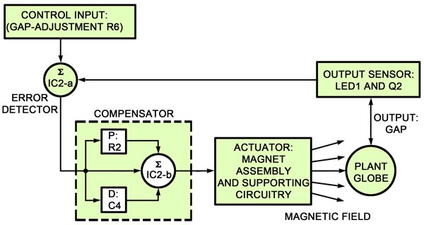
Fig. 5. This block diagram shows how the sections of the Levitator work together to resemble the models of closed-loop systems examined in Figs. 2 and 3.
The reference or control input is set by potentiometer R6 and resistor R8; that fixed resistor sets a minimum resistance value for the reference circuit. If R8 was not present and the wiper of R6 were turned to its lowest setting, a short circuit would exist from the emitter of Q2 to ground (which could damage Q2). Current from Q2 is directed through R6. That current is proportional to the gap between the magnet and the globe under it. You can set the desired gap distance by adjusting R6.
One section of an LM324 quad op-amp, IC2-a, is used as an error-detector. If R6 is set high, a given gap will result in a higher error voltage being generated by the error detector than if R6 were set low.
The compensator of the circuit consists of IC2-b, R1f R2, C4, R3, and R5. That compensator actually has two inputs, which both have the error signal from IC2-a applied equally to them. One input is through R2, the stability-adjustment potentiometer; the input coming in via R2 is the proportional (P) input to the compensator. The other input comes in through C4. That input is the derivative (D) input for the compensator. The compensator does not have an integral (I) input. Resistor R1 is a feedback resistor for IC2-b, and R3 and R5 bias the op-amp to operate on a single 12-volt supply.
The magnet assembly is made up of coil L1 and thermal-fuse F1. Because F1 is supposed to stop current flow when the magnet overheats, the fuse should be wired as part of coil L1 (more on that later). Both the magnet assembly and its supporting circuitry (C1, D1, M1, Q1, and R7) make up the actuator. The input to the actuator is the error signal from the gate of Q1, an IRF510 MOSFET transistor, and the output is the magnetic field from the magnet assembly.
Capacitor C1 filters "noise" and diode D1 protects Q1 from large voltage spikes that can occur across the" magnet assembly when the unit is turned off quickly. Meter M1 provides an indication of how much voltage is present in the magnet.
The magnet assembly transistor Q1, and resistor R7 are configured as a power amplifier with a gain of about 20. Transistor Q1 is configured as a common-source amplifier, meaning that the input signal is applied to its gate, and the output signal is taken off of its drain. The impedance of the drain circuit is the magnet resistance, or about 10 ohms, and the impedance of the source circuit is equal to the value of R7, 0.47 ohms.
To see how all the circuit components work together, look at Fig. 5, a block diagram of the Magnetic Ball Levitator. That's essentially the same type of diagram that was used in the earlier discussion of closed-loop systems.
Let's begin with the unit turned on and the ball suspended beneath the magnet a little closer than it should be. When the ball moves too close, more current flows in Q2, and the voltage across R6 increases. The error signal out of IC2-a then goes positive and couples to IC2-b through R2. Op-amp IC2-b amplifies and inverts the signal applying it to the gate of Q1. That negative signal is inverted and amplified, causing voltage on the drain of Q1 to go positive. As a result, less current flows in the magnet windings, which means less magnetic force is applied to the ball.
As the ball drops away from the magnet, the reverse occurs, Less current flows through Q2, which will result in more current flowing through the magnet. The compensator of the circuit keeps that back and forth motion of the ball stable so that it appears to be floating. Remember, potentiometer R2 can be used to adjust the level of that stability.
This article is reprinted from Popular Electronics, May 1996.
| < Previous | Page 7 of 9 | Next > |
©1998-2026 Barry Hansen