Magnetic Levitation
Levitation from 1996 Popular Electronics
- Introduction
- How It Works
- Control Systems
- Open or Closed?
- Basics of PID
- Schematic
- Circuit
- Construction
- Adjustment
Construction
The author's prototype for the Levitator was built on two perforated boards and mounted in a case measuring 71/2 x 10 x 31/2 inches. One board contains all the high-power components.
To begin assembly of the high-power component board, mount capacitors C1 and C4 and resistor R7. Then go on to install diode D1 and bridge-rectifier BR1. Position the board near the back of the case.
Mount the rest of the capacitors and fixed resistors on the other board. Next install IC1 and IC2 on that board, using an 1C socket for IC2. Position the board near the front of the case.
Now it's time to add the off-board components. Drill holes in the front of the project case to accommodate potentiometers R2 and R6, and install them. Go on to make holes for M1 and S1, and mount those parts as well.
Next drill a hole on the back panel and mount fuse F2. Also drill holes for the heat sink specified in the parts list. Transistor Q1 mounts on that heat sink. Although the heat sink might seem a little large for Q1, it is necessary because the unit controls up to 2 amps of current at up to 36 volts. That results in a lot of power to dissipate.
Drill another hole in the rear of the case to pass through a power cord. Connect that cord to transformer T1 and mount the latter near the back of the case. You can then complete all the in-case wiring.
Next, drill holes on the back of the case to mount a 1-inch-diameter PVC coupling. That coupling will be used to support the magnet arm made of 3/4-inch PVC pipe. When placed into that coupling, the magnet-arm can then freely turn and be easily removed again. Such a design provides a convenient way to lay the arm down flat on the side of the unit for storage purposes.
To make the magnet arm, you will need to bend a piece of PVC tubing to create an L shape. Cut a 3-foot-length section of the material to work with. Heat the middle 9 inches of the tube gradually and evenly; you can use a gas-range burner, a butane torch, or a heat gun to do that. After the 9-inch section you are heating starts to get rubbery, carefully bend the tube around a large coffee can (a 39-ounce can has a 6-inch diameter, which is perfect) to make a 90° angle. If you try to bend the tube with out using a form, the tube will deform and collapse.
After the tube cools, cut it so that the long part of the L-shaped tube is 12-inches long and the short part is 6-inches long. Drill a 5/32-inch hole in the underside of the short end of the mount, about 1/2 an inch back from its end. The screw that is used to hang the magnet from the mount will pass through that hole.
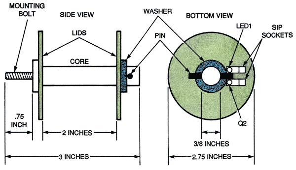
Fig. 6. When building your magnet assembly, use this diagram as a guide.
Now you can put together the magnet assembly; refer to Fig. 6 as you do so. The core of the magnet is a 3/8-inch-thick, 12-inch-long nail (perhaps it should more appropriately be called a spike). Drill a 5/32-inch-wide hole 1/2 an inch into the head of the nail. Next cut the head off of a 2-inch-long 10-24 bolt. Fill the hole in the nail with metal epoxy and drop the cut-off end of the bolt into the hole. When the epoxy hardens, you will have a solid mount with which to hang the magnet assembly from the magnet arm.
Drill 3/8-inch holes through the center of 2 orange-juice-can lids, and use a hand file to remove any burrs, which otherwise could short out the windings of the magnet if left in place. Slide the lids onto the nail, and separate them by a distance of 2 inches, as shown in Fig. 6. Then put on a washer and mark where a pin hole should be made on the nail to support the bottom lid. Use a 7/64-inch drill to make that hole. Cut off a 3/4-inch length of coat hanger to use for the pin, and insert it.
To make the magnet you will have to wind 520 feet of 22-gauge magnet wire onto the nail core. There is an easy way to do that: Close the chuck of a hand drill around the point of the nail. Loop the free end of the wire around the core a few times to lock it in place, then set the drill to low and wind the rest of the wire onto the bobbin. After the wire is wound onto the bobbin, use a hacksaw to cut the 12-inch-long nail down to the approximate size shown in Fig. 6. With a hand file, remove any burrs or rough spots from the end of the core.
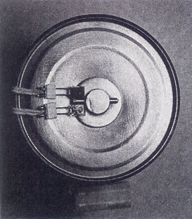
Fig. 7. When building your magnet assembly, use this diagram as a guide.
Then next step is to mount LED1 and Q2 next to each other on the magnet assembly, using two sections of an SIP socket. Position LED1 and Q2 so that the pin at the bottom of the magnet assembly is between them. When you'e done that, glue the SIP socket to the bottom can lid (you might have to rough up the lid with a wire brush or some fine-grit sandpaper first).
When the glue dries, give LED1 and Q2 a gentle twist so that they are pointing towards each other slightly. That allows the reflected light to bounce from LED1 to the globe to Q2 more efficiently. If you don't bend them like that, the sensor might only have a very short range.
Unwind a couple of turns from the magnet coil and cut the wire. Then solder thermal-fuse F1 in series with the magnet winding, and rewind the few turns you unwound. The fuse is now part of the coil.
Connect a 6-contact power socket (SO1) to the leads of LED1, Q2, and the magnet. Connect a matching 6-contact plug (PL1) to 3-foot lengths of wire, feed the other ends of the wire through the magnet arm, and make the proper connections to the circuit (using the schematic in Fig, 4 as a guide).
Insert the mounting bolt of the magnet assembly into the hole drilled in the short end of the arm, and place a nut over the bolt with a pair of needle-nose pliers. Holding the nut still, turn the magnet assembly to screw the nut onto the mounting bolt, Connect PL1 and SO1 together, insert the arm into its coupling, and your Levitator is ready to use.
This article is reprinted from Popular Electronics, May 1996.
| < Previous | Page 8 of 9 | Next > |
©1998-2026 Barry Hansen