Magnetic Levitation
Levitation
- Introduction
- Why
- Other Maglev
- Hard Drive Maglev
- Schematic
- Parts List
- Buying Parts
- Woodworking
- Other's
- Photographs
- Infrared Emitter
- Photodetector
- Reference Det
- Difference Amp
- Feedback Loop
- Loop Equations
- Bode Plot
- Phase Lead
- Output Amp
- Coil Driver
- PWM
- Lifting Coil
- PSPICE
- Build Time
- PCB
- Power Supplies
- Setup
- Test Power
- Test IR Emitter
- Test Signal Det
- Test Ref Det
- Adjust Sensing Res
- Test Diff Amp
- Test Non-Invert Amp
- Test Coil Driver
- Test Lifting Coil
- Results
Phase Lead Network
The magnetic levitator is not stable with only position information. (Believe me, I've been there!) The problem is this: suppose the ball is a little higher than the reference point. The circuit reduces the coil strength to allow the ball to go down. But! It doesn't turn on the coil again until the ball is past the reference spot. The ball has picked up some speed, and now it's too late for the coil to overcome both the speed and weight of the ball at the additional distance. Remember that a coil's strength drops off rapidly over distance. So the ball drops out. We fix this problem by detecting the ball's speed even before it moves past the reference point, and adjusting the coil strength to anticipate the new position.
This circuit uses a capacitor to get both speed and position information. It is connected in an arrangement commonly known as a "phase lead network". Let's look at the Bode plot of these networks, and then study our levitator's network more closely.
Bode Plot of Phase Lead Network
 A
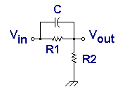
general purpose phase advance schematic is shown. This network becomes a voltage divider at very
low frequencies. It has unity gain at very high frequencies. In between, the transition is very
much like the phase lag seen on the previous page.
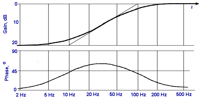
The time constant of the lower break frequency is R1C, and the ratio of break frequencies is the reciprocal of the gain (attentuation), resulting in the Bode plots shown below.

The sample Bode plot above is only meant to illustrate how a phase lead network can modify the gain and phase characteristics of a transfer function. Properly chosen values can move the two break points to a wide variety of possible frequencies.
The Levitator's Phase Lead Network
First, a little disclaimer, and a plea for help. I don't know why, but adding this circuit made my levitator stable. Do you know why? Can you tell me how to analyze the transfer functions of the remaining parts of the levitator?

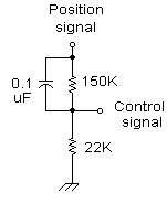
Look at the output from pin 6, slightly redrawn at left. Let's ignore the capacitor for a moment.
The 150K and 22K resistors form a divider circuit. It reduces the voltage by the ratio of the
two resistors. The "gain" will multiply the position signal by:
Gain = 22K / (22K + 150K) = 0.128
In other words it reduces the signal by a factor of eight. How come? Didn't we just amplify it by a factor of 9? Are we crazy or what?
The idea here is the signal through the capacitor bypasses the 150K resistor. This signal is the speed, ie, the derivative of the position signal. This speed signal goes through at full strength, and only the position signal is reduced. This results in the proper ratio of speed-to-position to stabilize the ball under the coil.
The lower breakpoint frequency is f1 = 1/(2 pi R1C) = 10.6 Hz.
The upper breakpoint requency is f2 = f1/Gain = 82.9 Hz.
If you still find the suspended object is unstable, and knocks around a couple times a second, then you probably want to change f1 to an even lower frequency. For example, suppose you want to cut f1 in half. Do this by:
- Swap out the 150K resistor, and put in a 75K resistor, i.e. about half the original value.
- This also lowered the upper breakpoint by four, because (a) the attenuation was cut in half and (b) the lower breakpoint was cut in half. So swap out the 22K resistor, and put in a 5.5K resistor, i.e. about one fourth the original value.
Other combinations are possible, but this is one way to get started in experimenting with values. Good luck! Kindly let me know what works for you!
| < Previous | Page 18 of 37 | Next > |
©1998-2026 Barry Hansen