Magnetic Levitation
Levitation
- Introduction
- Why
- Other Maglev
- Hard Drive Maglev
- Schematic
- Parts List
- Buying Parts
- Woodworking
- Other's
- Photographs
- Infrared Emitter
- Photodetector
- Reference Det
- Difference Amp
- Feedback Loop
- Loop Equations
- Bode Plot
- Phase Lead
- Output Amp
- Coil Driver
- PWM
- Lifting Coil
- PSPICE
- Build Time
- PCB
- Power Supplies
- Setup
- Test Power
- Test IR Emitter
- Test Signal Det
- Test Ref Det
- Adjust Sensing Res
- Test Diff Amp
- Test Non-Invert Amp
- Test Coil Driver
- Test Lifting Coil
- Results
Designing the Reference Detector

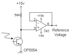
This optodetector measures the relative brightness of the infrared LED, along with the total ambient light. It provides a reference voltage to the op-amp.
This reference voltage is self-adjusting for small changes in operating conditions. It automatically helps adjust for changes in temperature, ambient light, supply voltage, LED brightness, aging of components, and so forth. Since this reference detector is affected in the same manner as the ball's optodetector, the op-amp will subtract its signal from the ball's to accurately sense the ball's position.
The op-amp is wired as a voltage follower to isolate the photodetector circuit from the next stage. It's not strictly necessary, but it does make design and testing a little easier. Note that you could replace the two 741 op-amps with a single package 324 dual op-amp.
This reference detector eliminates a potentiometer elsewhere in the circuit. One less adjustment to fiddle with! If you're lucky (like me) you won't have any potentiometer in the final device!
Mounting the Reference Detector
To make this work, mount the reference detector near the ball's optodetector. But not too near! The light path to the reference detector must not ever be obstructed by the ball. In this way the reference detector is affected equally by anything that happens to the ball's optodetector.
I mounted my detectors at the same height and about an inch apart horizontally. This gave good results, although I had to be careful about where my fingers went when I put the ball into the field of play. If anything blocks the light beam to the reference detector then the coil will not turn on.
Choosing the Sensing Resistor
You need to adjust the sensing resistor (nominally 56K) to provide a reference voltage in the midpoint of the other detector's operating range. This can be done once and then seldom if ever needs adjustment. I used a fixed resistor, but you might find it easier to use a 56K resistor plus a 20K potentiometer.
I also discovered that rotating the reference detector in its hole would adjust the reference voltage by up to a half-volt. Once the proper position was found I taped the detector into place. You should experiment with its rotation, too, before fiddling with resistance.
How do you choose this resistor? First measure the "clear" and "blocked" voltages on the other detector. (Use a high-impedance meter for measurements!) The "clear" voltage is when the path between emitter and detector is open and unblocked. The "blocked" voltage is when you cover the emitter (not the detector!) and measure the voltage due to ambient light. The signal detector will operate in this range. So the reference detector should be about halfway between these values, so the op-amp can properly amplify the difference.
Note: When the resistor goes up, its output voltage goes down.
Here's an example. One sunny day, I measured the signal detector's voltages to range from 7.0v to 9.0v. So I wanted to set the reference detector's voltage to 8.0v. Suppose I measured an initial reference voltage of 8.5v with a 56K resistor. This means I need to adjust the resistance to subtract 0.5v. This means increasing the resistance to get a lower voltage.
How much should the resistance change? Remember the current is constant; it only depends on the light and not the resistor. So we will find the current first, and use that to find the change in resistance.
The current in the resistor is voltage divided by its resistance:
I = (15.0v - 8.5v) / 56K = 0.116 mA
So to change the voltage by 0.5 volts, we can calculate the change in resistance by voltage divided
by current:
R = (0.5v) / (0.116 mA) = 4.3K
So in this example, I would have to add a 4.7K resistor to get the desired reference voltage.
Note the above is only an example; in my levitator I found that a 56K resistor already produced the desired reference voltage.
Operating Range

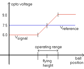
Here is a graph to illustrate what needs to be accomplished. The reference voltage establishes a midpoint position for the ball. The operating range is the range of voltages for which the detection circuit is linear. The signal voltage represents the maximum range of detectable ball positions. The reference voltage needs to be set near the midpoint of the operating range.
Your job is to establish a useful operating range, and then adjust the reference voltage to be in the midpoint of that range. If you're lucky, both detectors will be affected the same amount by changes in the ambient light level. If you get it right, then adjusting room lighting will move change voltages by the same amount. Good luck!
A Word About Resistor Tolerances
Notice the size of adjustments needed; the changes are around the same size as the common resistor's tolerance range! If you use garden-variety 10% tolerance resistors, then two identical-looking 100K resistors may be different by 20K. So don't count on buying "matched" resistors to make this work.
| < Previous | Page 13 of 37 | Next > |
©1998-2026 Barry Hansen