Magnetic Levitation
Levitation
- Introduction
- Why
- Other Maglev
- Hard Drive Maglev
- Schematic
- Parts List
- Buying Parts
- Woodworking
- Other's
- Photographs
- Infrared Emitter
- Photodetector
- Reference Det
- Difference Amp
- Feedback Loop
- Loop Equations
- Bode Plot
- Phase Lead
- Output Amp
- Coil Driver
- PWM
- Lifting Coil
- PSPICE
- Build Time
- PCB
- Power Supplies
- Setup
- Test Power
- Test IR Emitter
- Test Signal Det
- Test Ref Det
- Adjust Sensing Res
- Test Diff Amp
- Test Non-Invert Amp
- Test Coil Driver
- Test Lifting Coil
- Results
Designing the Photodetector Circuit

This optodetector measures the position of the ball by the amount of light transmitted by the infrared LED. This is a linear signal across the small area of the detector -- it is not just "on" and "off".
About the Detector Circuit
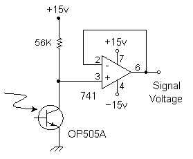
This circuit uses the optodetector as a light-controlled current source, operating in its linear range. Receiving additional light is the same as increasing its base current. Thus the amount of light falling on the detector will directly control the collector-emitter current. The current is converted to a voltage by the 56K ohm resistor connected from its collector to the positive supply voltage.
The op-amp is wired as a voltage follower to isolate the photodetector circuit from the next stage. Although not strictly necessary, the voltage follower ensures the detector's results are not affected by a VOM or voltmeter, or by the input resistance to the next stage.
Value of Sensor Resistor
The best value (for me) was a 56K resistor. This gives a two-volt signal on top of five volts of ambient noise. You want a large enough resistor so your voltage (that represents position) has a comfortable distance between either rail. Say, halfway between 15v and 0v, or around 7.5 volts.
The tiny current and high-impedance detector means you must use high impedance equipment.
- Do not try to measure the collector voltage with a VOM; its internal resistance is lower than 100K and it will not give accurate readings. Use a VTVM or a decent digital multimeter instead.
- Do not connect the detector to anything but an op-amp's input. It really needs to see a high-impedance input or its voltage output will be affected.
- Using an op-amp for a voltage follower makes a simple and convenient buffer. You can use any old voltmeter to measure the output voltage, and the optodetector is unaffected by other circuit changes.
Note that it might be a good idea to move the detection resistor to the ground side instead of the voltage side of the optodetector. (I didn't.) This would help isolate the signal voltage from power supply fluctuations. If you do, however, it has the side effect of inverting the signal and so you would need to add another signal inversion later in the overall circuit to compensate.
Distance Between Detector and Emitter
I started with 9 inches between the emitter and detector, but this turned out to be too far. I found that 100K collector resistor resulted in merely a one-volt signal difference between a "on" and "off" infrared LED. That is pretty small! That's only 10 microamps difference between the light getting through versus being blocked. Another good reason to eliminate stray sources of illumination on the optodetector.
I moved the emitter and detector closer together, so they're only 4.5 inches apart. I also moved the coil (and the light beam under it) to be two inches back from the front of the box. This gave me a four-volt signal, on top of ten volts of ambient light. The ambient light signal gets stronger at lesser distance because the detector could "see" the opposite side of the box more closely. Worse yet, when ambient levels went up (the sun came out, rare but possible in Seattle) the reflected light was enough to saturate the transistor, and the signal voltage stayed near zero volts whether or not the emitter's light beam was blocked.
I added black construction paper to one side of the box's interior, and the ambient noise was cut in half again without reducing the signal.
Adjusting the Photodetectors
 You
will probably need to adjust the photodetector's position. You want it exactly in the light beam
that passes just under the coil. One method is to drill an assortment of holes in the wooden
frame, and lightly press the photodetector into the hole that works best.
Click on the image at right for a closeup of a variety of holes I drilled. The vertical holes are for the optodetector; the horizontal row of holes are for the reference detector. You can see brown wires leading downward from the two optodetectors. The top holes were for my first coil, which was screwed in from above the wood frame. My second coil was screwed in upward from below, and so needed a lower set of holes.
| < Previous | Page 12 of 37 | Next > |
©1998-2026 Barry Hansen